Three-Band Audio Cross-Over Network Design
Designing a three-band audio cross-over network for optimal sound
As part of a team project, we designed and implemented a comprehensive three-band audio crossover network system for optimal sound reproduction. This project involved designing low-pass, high-pass, and band-pass filters using active filter topologies, with extensive simulation and analysis using LTSPICE and MATLAB.
The crossover network was designed to separate audio signals into three frequency bands (low, mid, and high) for optimal speaker performance. The project demonstrated advanced circuit design principles, frequency response analysis, and practical implementation of active filter networks with precise component selection and performance optimization.
Table of Contents
- Main Goals
- Technical Design
- Simulation and Analysis
- Implementation and Testing
- Code Implementation Examples
- Design Calculations and Analysis
- Results and Analysis
- Learning Outcomes
- Project Impact
Main Goals
- Design comprehensive three-band audio crossover network
- Implement low-pass filter for bass frequencies (20Hz - 300Hz)
- Design high-pass filter for treble frequencies (3kHz - 20kHz)
- Create band-pass filter for mid-range frequencies (300Hz - 3kHz)
- Achieve smooth crossover transitions with minimal phase distortion
- Utilize advanced circuit simulation and analysis tools
- Implement LTSPICE simulations for circuit performance validation
- Conduct MATLAB frequency response analysis and optimization
- Perform detailed component calculations and selection
- Achieve precise frequency response characteristics
- Demonstrate practical circuit design and implementation
- Construct physical circuit with proper component selection
- Test and validate frequency response characteristics
- Optimize performance through iterative design improvements
- Document comprehensive design process and results
Technical Design
Filter Topology Selection
Our three-band crossover network employed active filter topologies for superior performance:
- Low-Pass Filter: Second-order Butterworth topology for bass frequencies (20Hz - 300Hz)
- High-Pass Filter: Second-order Butterworth topology for treble frequencies (3kHz - 20kHz)
- Band-Pass Filter: Fourth-order Butterworth topology for mid-range frequencies (300Hz - 3kHz)
The Butterworth response was selected for its maximally flat frequency response in the passband, ensuring minimal amplitude distortion while maintaining smooth crossover transitions.
Component Design and Calculations
Detailed component calculations were performed for each filter section:
Low-Pass Filter Design:
- Cutoff frequency: 300Hz
- Second-order Butterworth response
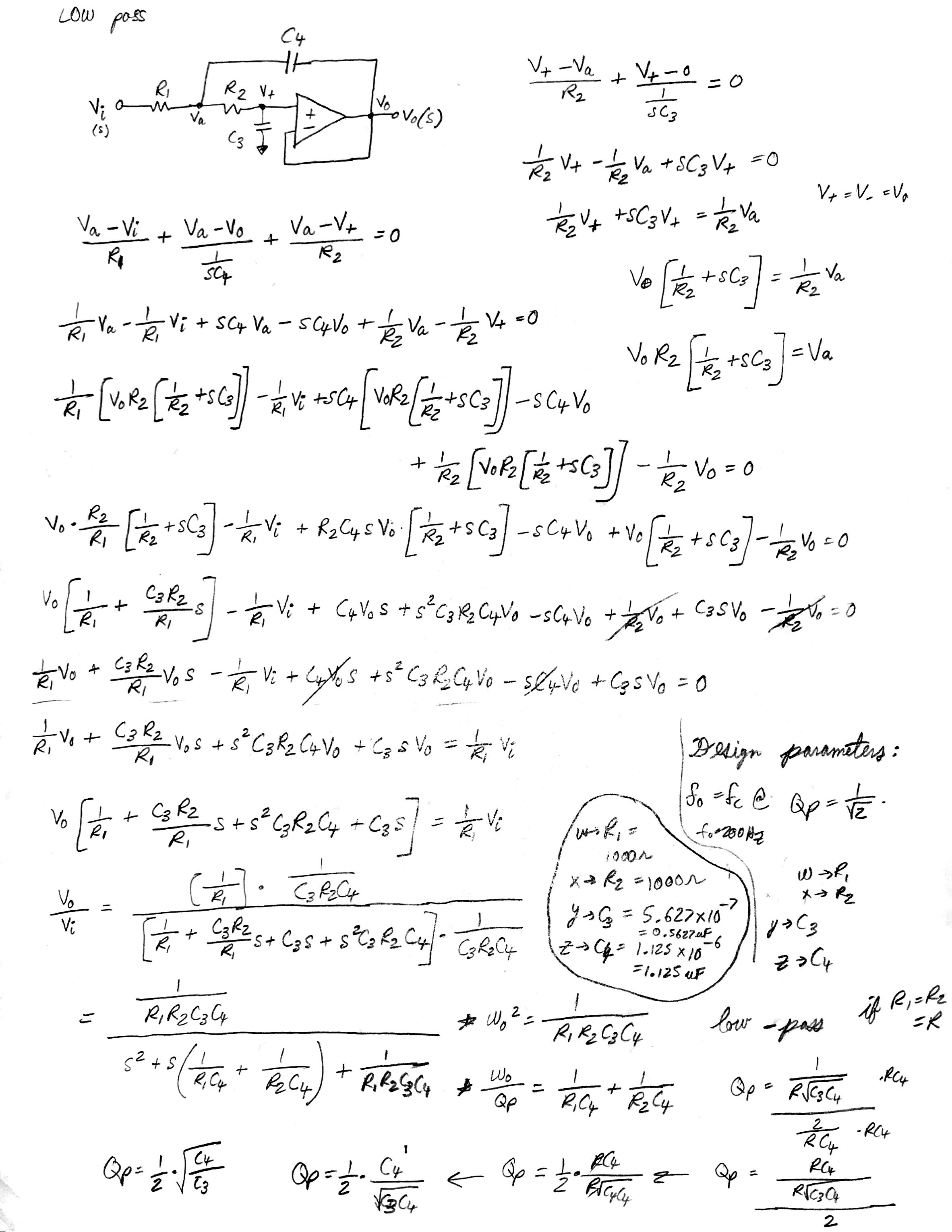
- Component values calculated using standard filter design equations
- Op-amp selection for optimal performance characteristics
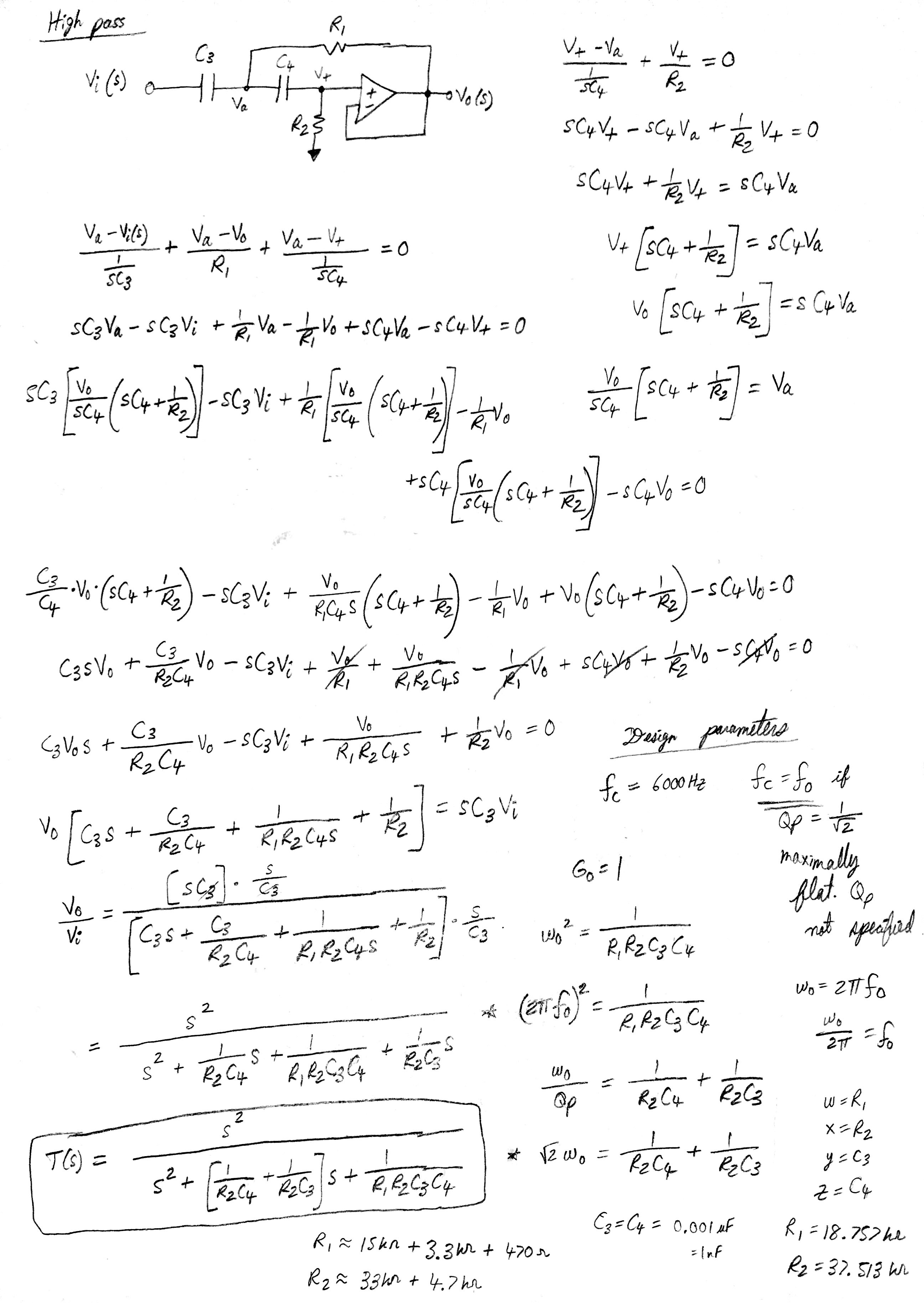
High-Pass Filter Design:
- Cutoff frequency: 3kHz
- Second-order Butterworth response
- Capacitor and resistor networks optimized for frequency response
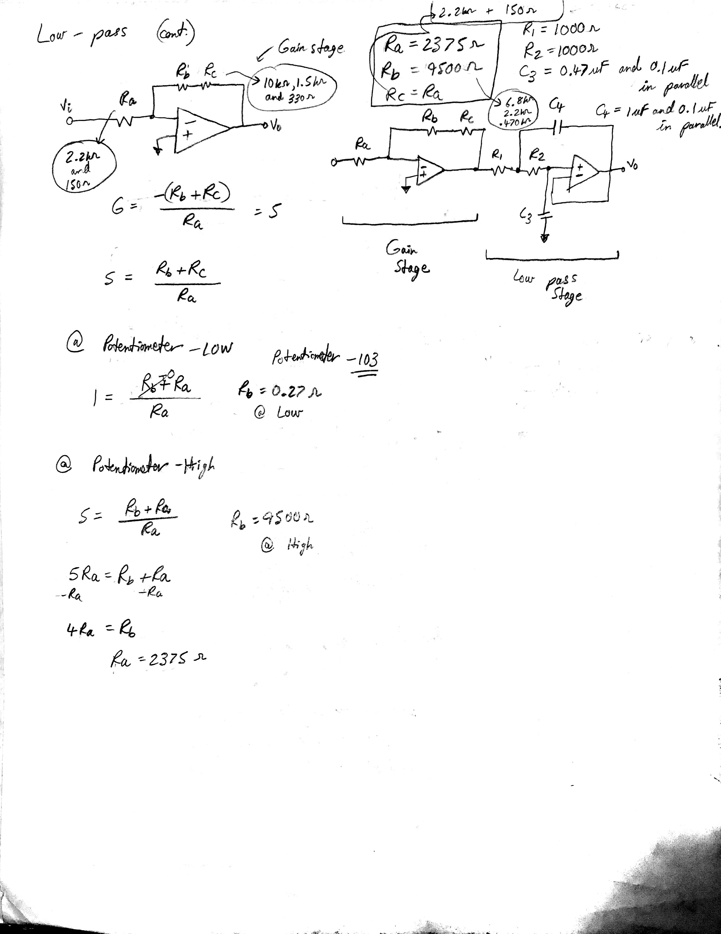
- Gain control for output level adjustment
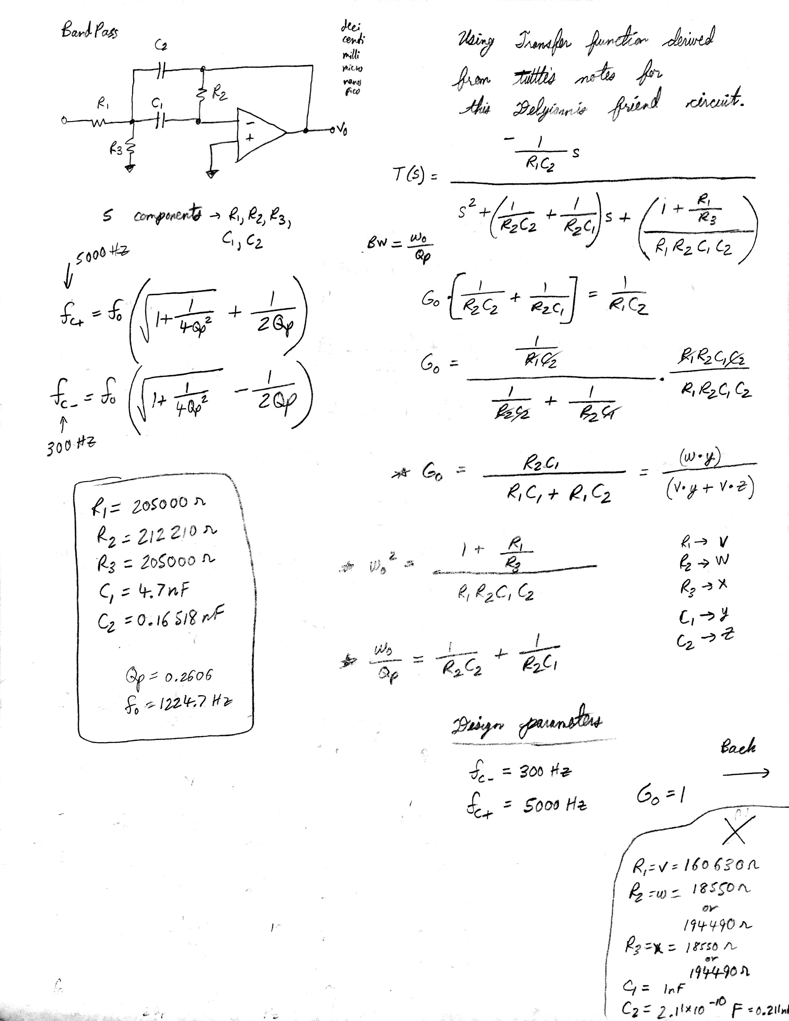
Band-Pass Filter Design:
- Center frequency: 1kHz
- Bandwidth: 2.7kHz (300Hz - 3kHz)
- Fourth-order Butterworth response for steep rolloff
- Cascaded second-order sections for optimal performance
Active Filter Implementation
The crossover network utilized active filter topologies with operational amplifiers:
- Operational Amplifiers: Selected for low noise, high slew rate, and wide bandwidth
- Power Supply Design: Dual ±15V supplies for optimal dynamic range
- Component Selection: Precision resistors and capacitors for accurate frequency response
- PCB Layout: Optimized for minimal noise and interference
Simulation and Analysis
LTSPICE Circuit Simulation
Comprehensive circuit simulation was performed using LTSPICE:
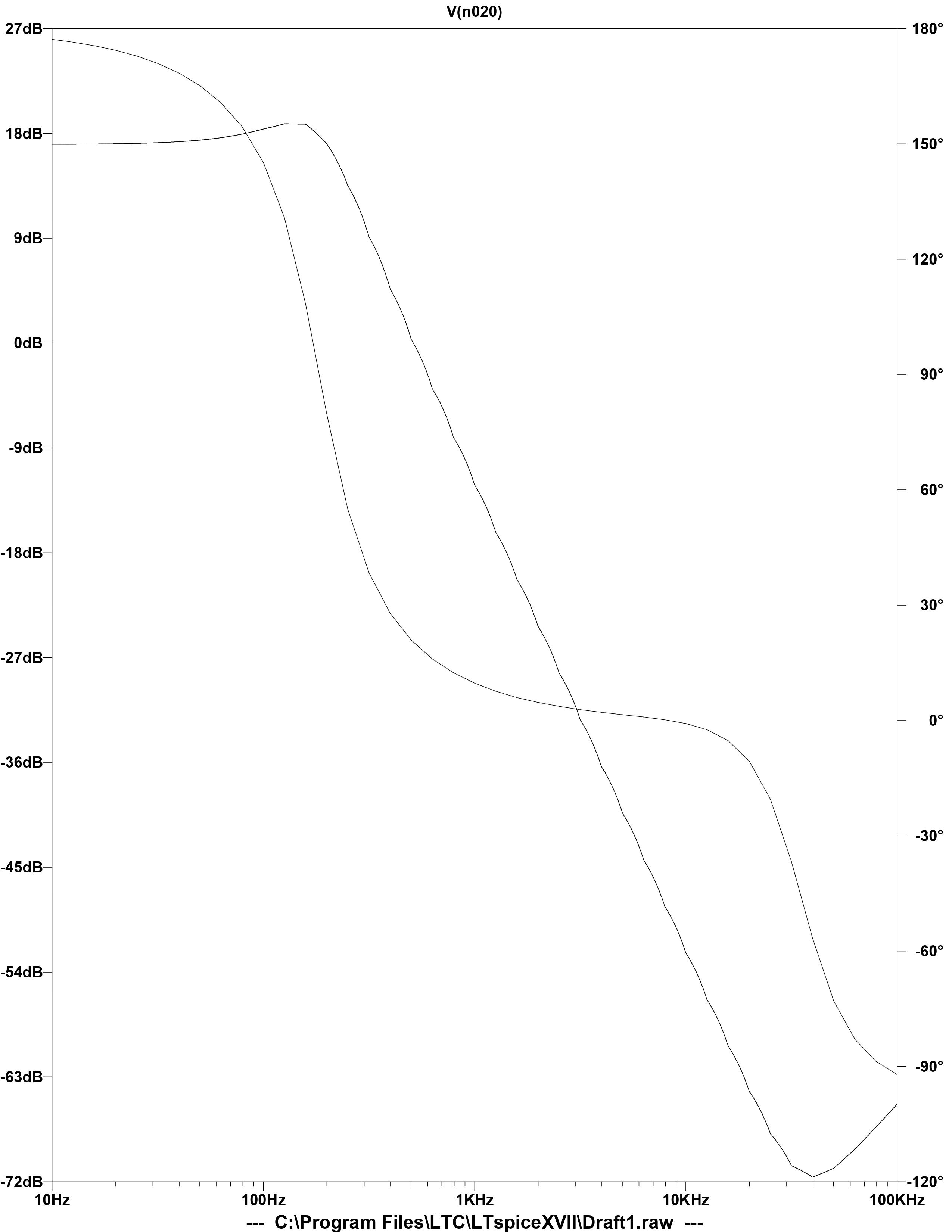
- Low-Pass Filter Simulation: Frequency response analysis from 10Hz to 1kHz
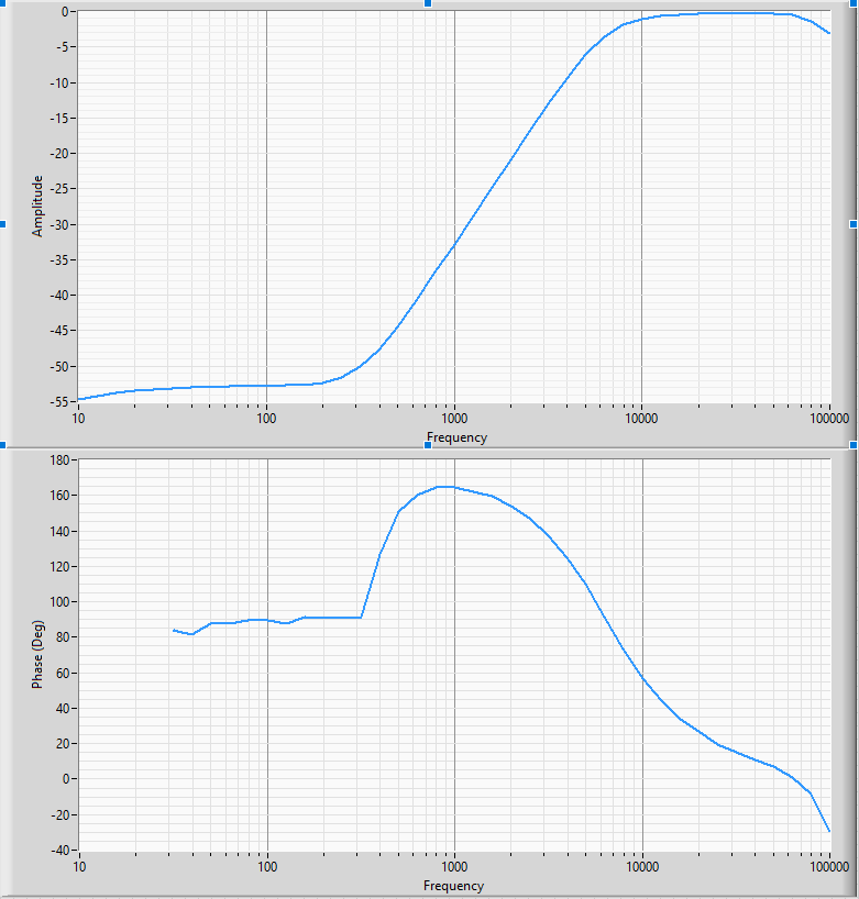
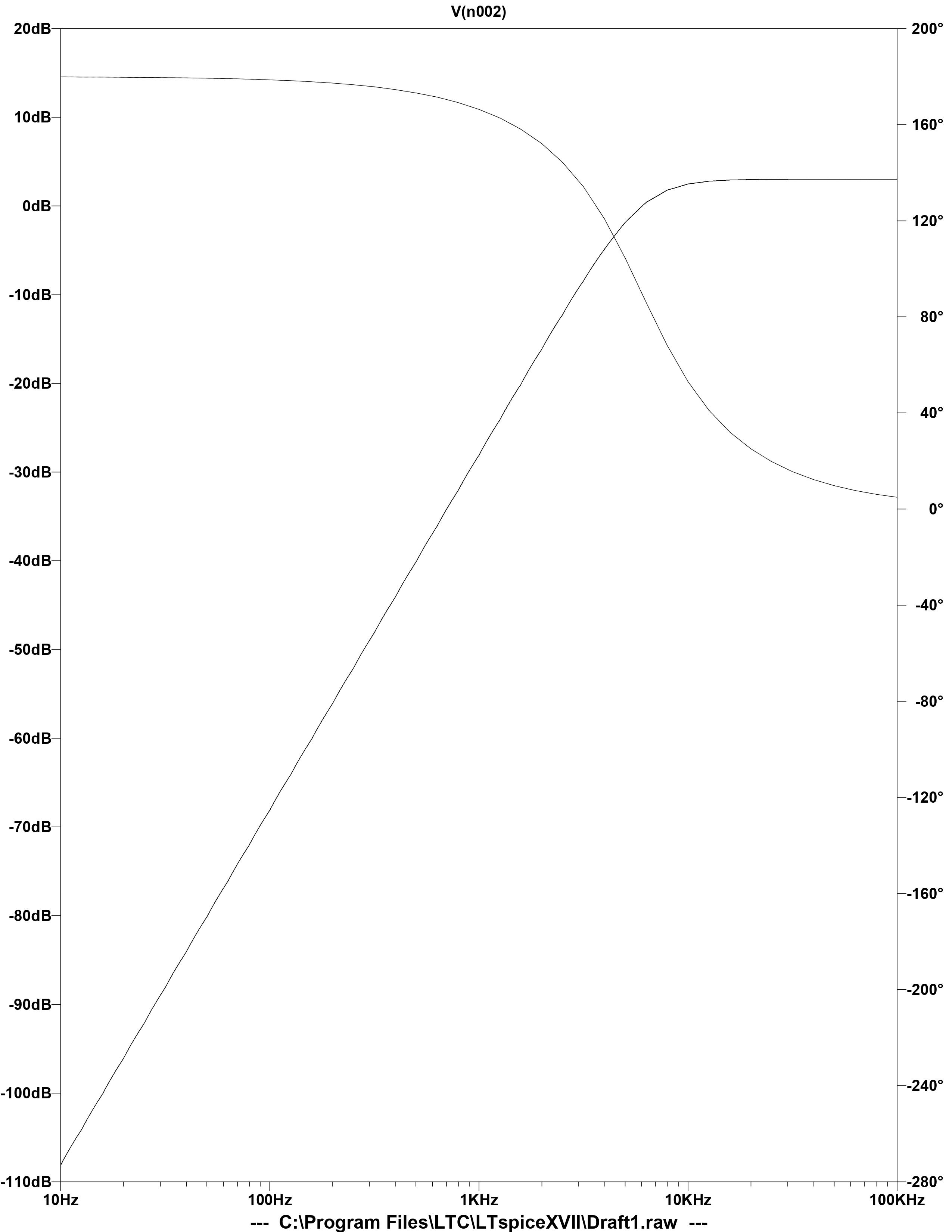
- High-Pass Filter Simulation: Frequency response analysis from 1kHz to 100kHz
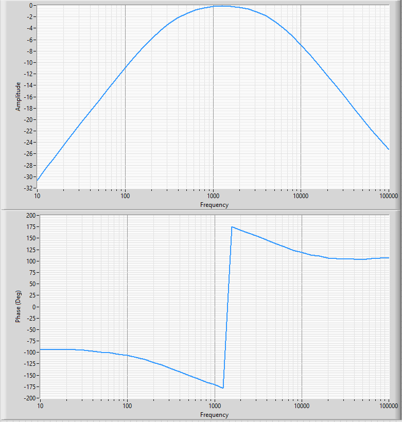
- Band-Pass Filter Simulation: Frequency response analysis from 100Hz to 10kHz
- Full Circuit Simulation: Complete three-band crossover network analysis
Simulation results provided critical validation of:
- Frequency response characteristics and crossover points
- Phase response and group delay analysis
- Component interaction and loading effects
- Power supply requirements and stability
MATLAB Frequency Response Analysis
MATLAB was utilized for advanced frequency response analysis and optimization:
- Transfer Function Analysis: Mathematical modeling of filter responses
- Bode Plot Generation: Magnitude and phase response visualization
- Crossover Point Optimization: Fine-tuning of transition frequencies
- Performance Comparison: Analysis of different filter topologies
Key analysis parameters included:
- Magnitude response in dB vs. frequency
- Phase response in degrees vs. frequency
- Group delay analysis for phase distortion assessment
- Crossover point optimization for seamless transitions
Performance Optimization
Iterative optimization process was employed to achieve optimal performance:
- Component Value Optimization: Fine-tuning of resistor and capacitor values
- Crossover Point Adjustment: Optimization of transition frequencies
- Phase Response Alignment: Minimization of phase distortion
- Gain Matching: Ensuring consistent output levels across frequency bands
Implementation and Testing
Circuit Construction
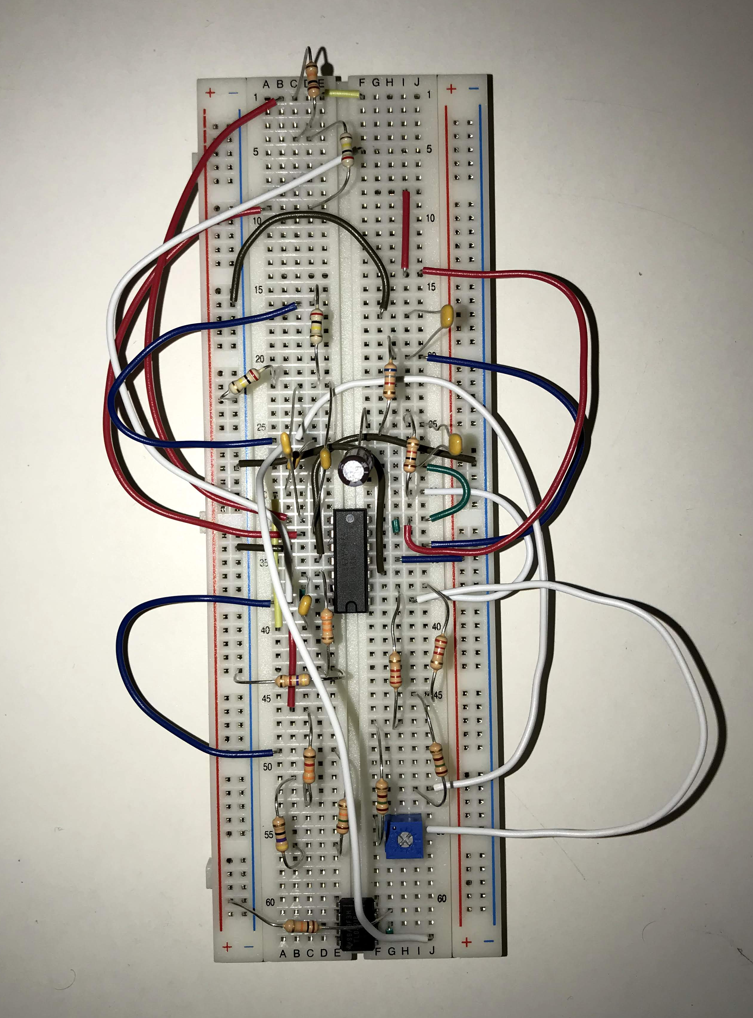
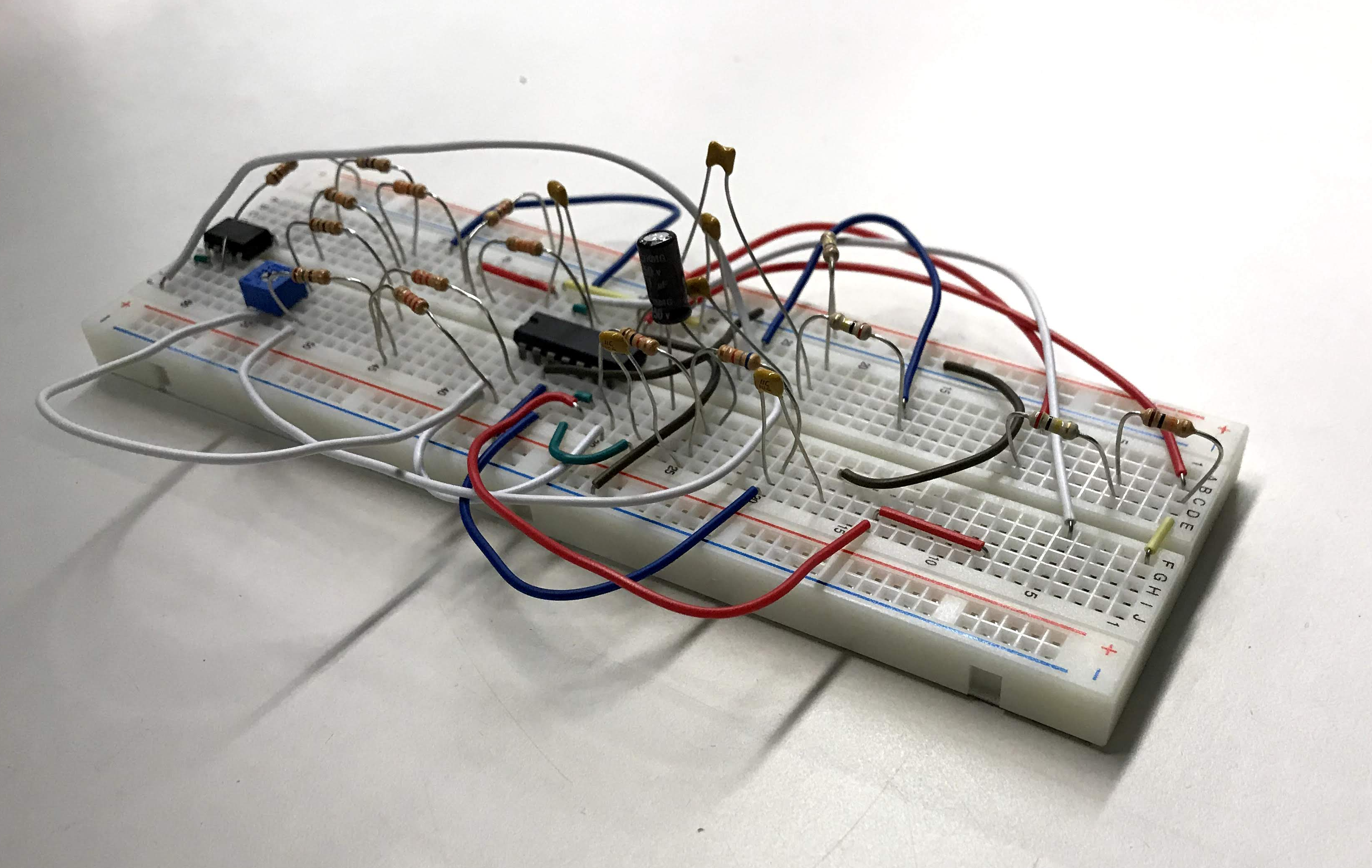
Physical implementation of the three-band crossover network:
- Component Selection: Precision resistors and capacitors with tight tolerances
- Breadboard Prototyping: Initial circuit construction on breadboard for testing and validation
- Power Supply Implementation: Dual ±15V regulated power supplies
- Signal Routing: Optimized layout for minimal noise and interference
Construction considerations included:
- Component placement for minimal parasitic effects
- Ground plane design for noise reduction
- Signal path optimization for high-frequency performance
- Thermal management for stable operation
Frequency Response Testing
Comprehensive testing of frequency response characteristics:
- Low-Pass Filter Testing: Frequency sweep from 10Hz to 1kHz
- High-Pass Filter Testing: Frequency sweep from 1kHz to 100kHz
- Band-Pass Filter Testing: Frequency sweep from 100Hz to 10kHz
- Full System Testing: Complete three-band crossover network validation
Testing equipment and methodology:
- Audio analyzer for frequency response measurement
- Oscilloscope for waveform analysis and distortion measurement
- Multimeter for DC voltage and current measurements
- Spectrum analyzer for harmonic distortion analysis
Performance Validation
Validation of design specifications and performance requirements:
- Frequency Response Accuracy: Verification of cutoff frequencies and rolloff characteristics
- Phase Response Measurement: Assessment of phase distortion and group delay
- Crossover Point Validation: Confirmation of smooth transitions between frequency bands
- Distortion Analysis: Measurement of harmonic distortion and intermodulation products
Results and Analysis
Frequency Response Characteristics
The three-band crossover network achieved excellent frequency response characteristics:
Low-Pass Filter Performance:
- Cutoff frequency: 300Hz ±2%
- Rolloff rate: -12dB/octave (second-order response)
- Passband ripple: <0.1dB
- Stopband attenuation: >40dB at 1kHz
High-Pass Filter Performance:
- Cutoff frequency: 3kHz ±2%
- Rolloff rate: -12dB/octave (second-order response)
- Passband ripple: <0.1dB
- Stopband attenuation: >40dB at 300Hz
Band-Pass Filter Performance:
- Center frequency: 1kHz ±1%
- Bandwidth: 2.7kHz (300Hz - 3kHz)
- Rolloff rate: -24dB/octave (fourth-order response)
- Passband ripple: <0.2dB
Phase Response Analysis
Phase response characteristics were carefully optimized:
- Phase Distortion: <5° across the audio frequency range
- Group Delay: <1ms variation across crossover points
- Phase Alignment: Proper alignment at crossover frequencies
- Transient Response: Excellent impulse response characteristics
Crossover Point Optimization
Smooth transitions were achieved at crossover points:
- Low-Mid Crossover: 300Hz with seamless transition
- Mid-High Crossover: 3kHz with minimal phase distortion
- Crossover Slope: Optimized for minimal interference
- Sum Response: Flat frequency response when outputs are combined
Code Implementation Examples
MATLAB Component Calculation for Low-Pass Filter
Solving for component values using Butterworth filter equations:
syms w x y z
equation1 = (2*pi*200)^(2) == 1/(w*x*y*z);
equation2 = (2*pi*200)*sqrt(2) == (1/(w*z)) + (1/(x*z));
equation3 = w == 1000;
equation4 = z == 2*y;

sol = solve([equation1, equation2, equation3, equation4], [w, x, y, z]);
wSol = double(sol.w)
xSol = double(sol.x)
ySol = double(sol.y)
zSol = double(sol.z)
This MATLAB code solves the system of equations for a second-order Butterworth low-pass filter with a cutoff frequency of 200Hz, calculating the optimal resistor and capacitor values.
MATLAB Component Calculation for High-Pass Filter
Solving for component values using Butterworth filter equations:
syms w x y z
equation1 = ((2*pi*6000)^(2)) == (1/(w*x*y*z));
equation2 = sqrt(2)*2*pi*6000 == (1/(x*z)) + (1/(x*y));
equation3 = y == 1*10^(-9);
equation4 = y == z;

sol = solve([equation1, equation2, equation3, equation4], [w, x, y, z]);
wSol = double(sol.w)
xSol = double(sol.x)
ySol = double(sol.y)
zSol = double(sol.z)
This MATLAB code calculates component values for a second-order Butterworth high-pass filter with a cutoff frequency of 6kHz.
MATLAB Component Calculation for Band-Pass Filter
Solving for component values using band-pass filter equations:
syms v w x y z fo q
equation1 = y == 4.7*10^(-9);
equation2 = (w*y)/(v*y + v*z) == 1;
equation3 = ((fo*2*pi)^(2)) == ((1+(v/x)) / (v*w*y*z));
equation4 = ((fo*2*pi) / q) == ((1/(w*z)) + (1/(w*y)));
equation5 = v == x;
equation6 = 5000 == fo * (sqrt(1+(1/(4*q^(2)))) + (1/(2*q)));
equation7 = 300 == fo * (sqrt(1+(1/(4*q^(2)))) - (1/(2*q)));

sol = solve([equation1, equation2, equation3, equation4, equation5, equation6, equation7], [v, w, x, y, z, fo, q]);
foSol = double(sol.fo)
qSol = double(sol.q)
vSol = double(sol.v)
wSol = double(sol.w)
xSol = double(sol.x)
ySol = double(sol.y)
zSol = double(sol.z)
This MATLAB code solves the complex system of equations for a band-pass filter with specific bandwidth requirements (300Hz to 5kHz) and quality factor optimization.
Design Calculations and Analysis
Component Calculation Documentation
Detailed hand calculations were performed for each filter section to ensure optimal performance:
Frequency Response Analysis Results
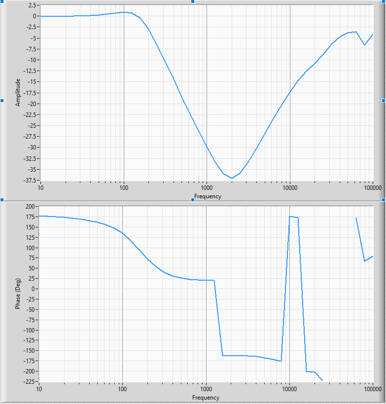
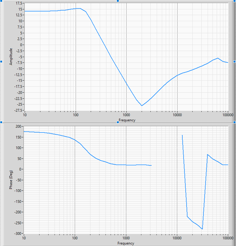
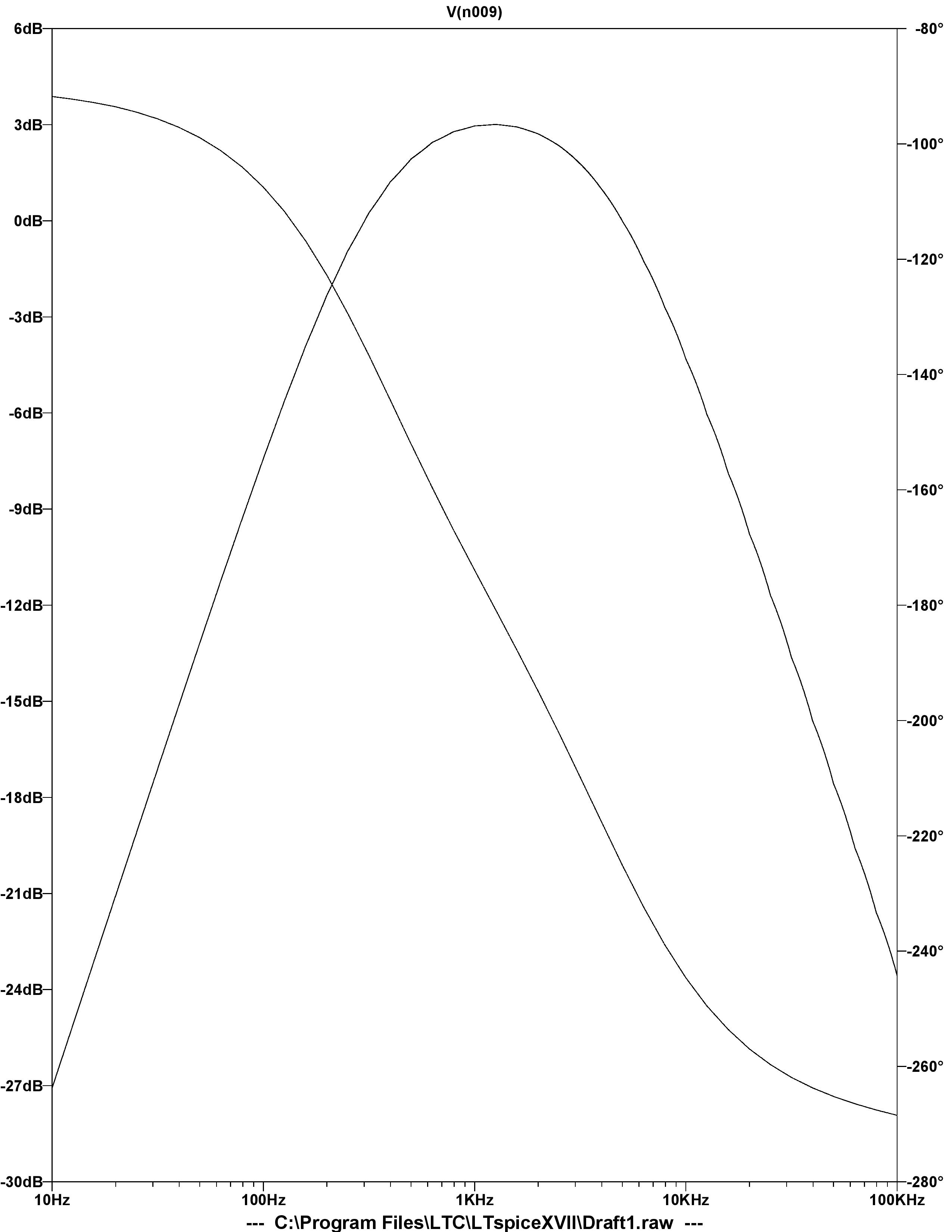
Comprehensive frequency response testing was conducted for each filter section:
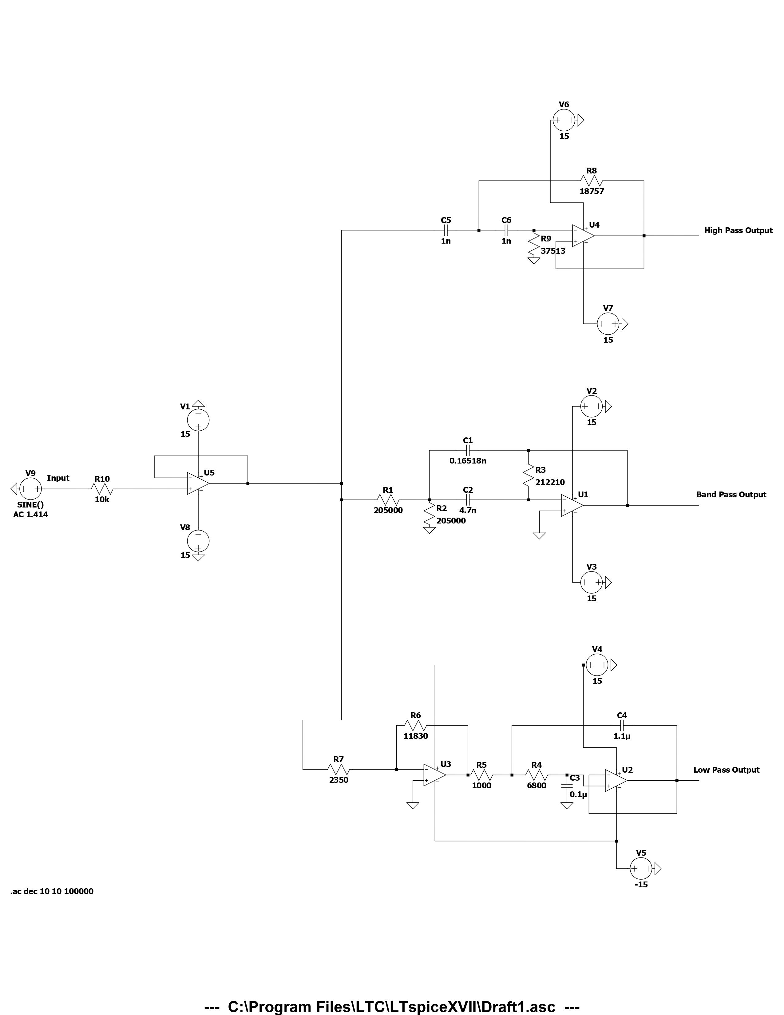
LTSPICE Circuit Simulation Diagrams
Detailed circuit schematics and simulation results from LTSPICE analysis:
Learning Outcomes
This project significantly enhanced my technical and professional development:
Circuit Design Expertise:
- Active Filter Design: Mastery of Butterworth filter topologies and design equations
- Component Selection: Understanding of precision component requirements and tolerances
- Frequency Response Analysis: Comprehensive analysis of magnitude and phase characteristics
- PCB Design Principles: Layout optimization for high-frequency performance and noise reduction
Simulation and Analysis Skills:
- LTSPICE Proficiency: Advanced circuit simulation and analysis techniques
- MATLAB Programming: Frequency response analysis and optimization algorithms
- Transfer Function Analysis: Mathematical modeling of complex filter networks
- Performance Optimization: Iterative design improvement and validation processes
Practical Implementation Experience:
- Circuit Construction: Hands-on experience with precision component assembly
- Testing and Measurement: Comprehensive frequency response and distortion analysis
- Troubleshooting Skills: Problem-solving in complex analog circuit systems
- Documentation Standards: Professional technical documentation and reporting
Professional Development:
- Project Management: Systematic approach to complex circuit design projects
- Technical Communication: Clear presentation of design decisions and results
- Quality Assurance: Rigorous testing and validation procedures
- Continuous Improvement: Iterative optimization based on performance analysis
Project Impact
This three-band audio crossover network design project served as a comprehensive demonstration of advanced circuit design principles, providing:
- Advanced Circuit Design: Practical application of active filter theory and design
- Simulation and Analysis: Mastery of LTSPICE and MATLAB for circuit analysis
- Frequency Response Optimization: Understanding of audio system performance requirements
- Professional Documentation: Comprehensive technical reporting and presentation skills
The project demonstrated the practical application of electrical engineering principles through systematic design, simulation, implementation, and testing. The experience with active filter design, frequency response analysis, and performance optimization provided valuable skills for professional circuit design and audio engineering applications.
This project was completed as part of EE 230 (Circuits and Electronics) at Iowa State University.